|
|
|
|
|
|
|
|||||||||||||||||||||||||||||||||||||||||||
IIM Input isolation modules |
|
|
||||||||||||||||||||||||||||||||||||||||||||||
|
|
|
|
|
|
|
|||||||||||||||||||||||||||||||||||||||||||
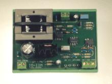
OverviewThe
IIM isolation modules take a voltage or current input signal and produce a
voltage output signal which floats with reference to the input signal ground Applications
include interfacing modern sensors with old or non-standard controller
inputs. |
|
|
|
|||||||||||||||||||||||||||||||||||||||||||||
|
|
|
|
|
|
|
|||||||||||||||||||||||||||||||||||||||||||
Specifications |
|
|
|
|
||||||||||||||||||||||||||||||||||||||||||||
Features ·
Floating
voltage outputs ·
0-5
V and 0-10V inputs (IIM-V) ·
4-20mA
input (IIM-I) ·
0-20mA
input available on request ·
Sensor
powered from IIM ·
24V
AC powered ·
DIN
rail mounting |
Connection diagrams
|
|
||||||||||||||||||||||||||||||||||||||||||||||
|
|
Power connections |
|
||||||||||||||||||||||||||||||||||||||||||||||
|
|
|
|
||||||||||||||||||||||||||||||||||||||||||||||
|
|
IIM-V sensor side: |
|
||||||||||||||||||||||||||||||||||||||||||||||
|
|
|
|
||||||||||||||||||||||||||||||||||||||||||||||
|
|
IIM-I sensor side: |
|
||||||||||||||||||||||||||||||||||||||||||||||
|
|
|
|
||||||||||||||||||||||||||||||||||||||||||||||
|
|
Controller side: |
|
||||||||||||||||||||||||||||||||||||||||||||||
|
|
|
|
||||||||||||||||||||||||||||||||||||||||||||||
|
|
|
|
||||||||||||||||||||||||||||||||||||||||||||||
|
|
Note:
Grounds on sensor side are common to both signal and power |
|
||||||||||||||||||||||||||||||||||||||||||||||
|
|
|
|
|
|
|
|||||||||||||||||||||||||||||||||||||||||||
Cleaning |
|
|
|
|
|
|||||||||||||||||||||||||||||||||||||||||||
|
Under
normal circumstances, interface modules should not require cleaning. However they can be cleaned by
disconnecting and wiping with isopropanol.
They must be completely dry before reconnection |
|
|||||||||||||||||||||||||||||||||||||||||||||||
Alphaglen Laboratories LimitedUnit 13, Millbrook Business Park, Jarvis
Brook, Crowborough, East Sussex TN6 3JZ
Tel: 01892 664224 Email: info@alphaglen.co.uk Web: www.alphaglen.co.uk |
|
|||||||||||||||||||||||||||||||||||||||||||||||
|
Whilst every effort has been made to ensure the accuracy of
this specification, Alphaglen Laboratories Ltd cannot accept responsibility
for damage, injury, loss or expense resulting from errors or omissions. In the interest of technical improvement,
this specification my be altered without notice Issue 2001/01 |
|
|||||||||||||||||||||||||||||||||||||||||||||||
|
|
|
|
|
|
|
|||||||||||||||||||||||||||||||||||||||||||


|
|
|
|
|
|
|||||||||||
IIM Input isolation modules |
|
|
|
|
|||||||||||
|
|
|
|
|
|
|||||||||||
Installation |
|
|
|
|
|||||||||||
|
|||||||||||||||
|
|
|
|
|
|
|||||||||||
Connection of IIM-I to sensor |
|
|
|
Connection of IIM-V to sensor |
|||||||||||
|
|
|
||||||||||||||
|
|
|
|
|
|
|||||||||||
|
|
|
|
|
|
|||||||||||
|
|
|||||||||||||||
|
|
|
|
|
|
|||||||||||
|
|
|||||||||||||||
|
|
|
|
|
|
|||||||||||
Safety |
|
|
|
|
|||||||||||
|
The
IIM must be installed only by a suitably qualified electrician and may not be
safe if installed incorrectly. The
IIM must be used only in an installation which incorporates a switch or
circuit breaker. Terminals must be
disconnected from hazardous voltages before screwing or unscrewing. A 5A fuse on the 24V supply is
recommended. If the IIM is connected
to a hazardous voltage, the IIM must be mounted inside a cabinet and must not
be accessible from the outside with a 100mm long probe |
|||||||||||||||
|
|
|
|
|
|
|||||||||||
Alphaglen Laboratories LimitedUnit 13, Millbrook Business Park, Jarvis
Brook, Crowborough, East Sussex TN6 3JZ
Tel: 01892 664224 Email: info@alphaglen.co.uk Web: www.alphaglen.co.uk |
|||||||||||||||
|
|
|
|
|
|
|||||||||||
|
Whilst every effort has been made to ensure the accuracy of this specification, Alphaglen Laboratories Ltd cannot accept responsibility for damage, injury, loss or expense resulting from errors or omissions. In the interest of technical improvement, this specification my be altered without notice Issue 2001/01 |
|||||||||||||||
|
|
|
|
|
Page 2 of 2 |
|||||||||||